Soft-Edged Shadows
by Anirudh.s Shastry
Introduction
원래 동적 그림자 기법은 한정된 방식으로만 가능했다. 그러나 강력한 프로그래밍 가능한 그래픽 하드웨어의 발전과 함께 동적 그림자 기법은 조명 매핑(light mapping) 과 같은 정적 기법이나 투영 그림자(projected shadow) 와 같은 약간 동적인 기법들을 거의 완벽히 대체하게 되었다. 동적 그림자 기법으로 일반적으로 사용되는 것은 그림자 부피(shadow volume)와 그림자 매핑(shadow mapping)이다.
A Closer look
그림자 부피는 닫힌 부피를 생성하기 위해서 조명 방향으로 기하도형을 밀어낸 것(extrusion)을 요구하는 기하도형 기반 기법이다. 그리고 나서 ray casting 을 통해서 씬 내의 그림자가 드리운 부분이 결정될 수 있다(일반적으로 스텐실 버퍼가 ray-casting 을 위해서 사용된다). 이 기법은 픽셀 단위로 정확하며 aliasing 문제를 발생시키지 않지만, 다른 기법들과 마찬가지로 자신만의 단점을 가지고 있다. 이 기법의 두 가지 큰 문제는 그것이 기하도형에 매우 의존적이며 fill-rate 에 민감하다는 것이다. 이 때문에 그림자 매핑이 천천히 대중화되어 가고 있다.
한편 그림자 매핑은 뷰의 조명 위치로부터의 씬 깊이를 렌더링하고 이 깊이 정보를 사용하여 씬 내의 어떠한 위치에 그림자가 드리워져야 하는지를 결정하는 것을 포함하는 이미지 공간 기법이다. 이 기법이 몇 가지 이점을 가지고 있기는 하지만, 그것은 aliasing 인공물과 z-fighting 을 피할 수 없다. 그러나 이에 대한 해결책이 존재하고 장점이 단점보다는 크기 때문에 이것이 이 기사를 위해서 내가 선택하는 기법이 될 것이다.
Soft shadows
딱딱한 그림자는 씬의 사실감을 떨어뜨린다. 그러므로 우리는 씬의 가시 품질을 증가시키기 위해서 부드러운 그림자를 써서 속일 필요가 있다. 매우 열광적인 많은 PHD 학생들이 부드러운 그림자를구현하기 위한 기법을 설명하는 문서를 가지고 왔다. 그러나 이 기법들 중 대부분은 복잡한 씬을 고려했을 때 실시간에 구현하기 어려웠다. 이들 기법들 중 약간의 제약을 극복할 수 있는 하드웨어를 가지게 될 때까지 우리에게는 더 현실적인 기법이 필요할 것이다.
이 기사에서 나는 그림자 맵을 사용해 부드러운 모서리를 가진 그림자를 생성하기 위한 이미지 공간 기법을 제시한다. 이 기법은 완벽한 부드러운 그림자를 생성하지는 않는다(no umbar-penumbra). But it not only solves the aliasing problems of shadow mapping, it improves the visual quality by achieving aesthetically pleasing soft edged shadows.
So how does it work?
먼저 우리는 뷰에서의 조명 위치로부터의 씬 깊이를 부동 소수점 버퍼로 렌더링함으로써 일반적인 그림자 맵을 생성한다. 그리고 나서 그림자를 사용해 씬을 렌더링하는 대신에 그림자가 있는 영역을 스크린 크기의 버퍼로 렌더링한다. 이제 bloom 필터를 사용해 블러링(blur)하고 그것을 스크린 공간에 있는 씬에다가 다시 투영한다. 쉬워 보이는가?
이 기사에서 우리는 집중 조명(spot light)만을 다룬다. 그러나 이 기사는 점 조명(point light)를 다루기 위해서도 쉽게 확장될 수 있다.
여기에 그 단계가 나와 있다 :
- 부동 소수점 버퍼에 씬의 깊이를 씀으로써 일반적인 그림자 맵을 생성한다.
- 깊이 비교 후에 씬 내의 그림자 영역을 고정 소수점 텍스처에 조명 없이 넣는다.
- 위의 버퍼를 bloom 필터를 사용해 블러링한다( 이 기사에서는
sperable Gaussian 필터를 사용하지만, 다른 필터를 사용해도 상관없다).
- 스크린 공간에서 씬에 블러링된 버퍼를 투영하여 전체 조명을 따라 존재하는
cool soft-edged 그림자를 획득한다.
Step1 : Rendering the Shadow map
먼저 우리는 씬 깊이를 저장할 수 있는 텍스처를 생성할 필요가 있다. 우리는 이를 렌더 타겟으로 사용할 것이기 때문에, 우리는 텍스처 서피스 데이터를 저장할 서피스도 생성할 필요가 있을 것이다. 그 텍스처는 반드시 부동 소수점이어야 한다. 왜냐하면 깊이 값의 범위가 넓기 때문이다. R32F 포맷은 만족스런 정밀도를 가지고 있으며, 그래서 우리는 그것을 사용할 것이다. 여기에 텍스처를 생성하는 데 사용된 코드가 있다.
if( FAILED( g_pd3dDevice->CreateTexture( SHADOW_MAP_SIZE,
SHADOW_MAP_SIZE, 1,
D3DUSAGE_RENDERTARGET, D3DFMT_R32F,
D3DPOOL_DEFAULT, &g_pShadowMap,
NULL ) ) )
{
MessageBox( g_hWnd, "Unable to create shadow map!",
"Error", MB_OK | MB_ICONERROR );
return E_FAIL;
}
g_pShadowMap->GetSurfaceLevel( 0, &g_pShadowSurf );
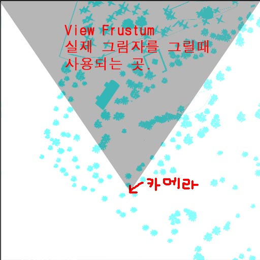
이제 그림자 맵을 생성하기 위해서 우리는 씬의 깊이를 그림자 맵에 렌더링할 필요가 있다. 이를 위해서 조명의 world-view-projection 행렬을 사용해 씬을 렌더링해야만 한다. 아래에 그 행렬을 생성하는 방법이 나와 있다.
D3DXMatrixLookAtLH( &matView, &vLightPos, &vLightAim, &g_vUp );
D3DXMatrixPerspectiveFovLH( &matProj, D3DXToRadian(30.0f), 1.0f, 1.0f, 1024.0f );
matLightViewProj = matWorld * matView * matProj;
아래에 씬 깊이를 렌더링하기 위한 정점 및 픽셀 쉐이더가 나와 있다.
struct VSOUTPUT_SHADOW
{
float4 vPosition : POSITION;
float fDepth : TEXCOORD0;
};
VSOUTPUT_SHADOW VS_Shadow( float4 inPosition : POSITION )
{
VSOUTPUT_SHADOW OUT = (VSOUTPUT_SHADOW)0;
OUT.vPosition = mul( inPosition, g_matLightViewProj );
OUT.fDepth = OUT.vPosition.z;
return OUT;
}
여기에서 우리는 조명의 위치에 world-view-projection 행렬(g_matLightViewProj)을 곱했으며, 변환된 위치의 z 값을 깊이로 사용했다. 픽셀 쉐이더에서 우리는 색상값으로 그 깊이를 출력한다.
float4 PS_Shadow( VSOUTPUT_SHADOW IN ) : COLOR0
{
return float4( IN.fDepth, IN.fDepth, IN.fDepth, 1.0f );
}
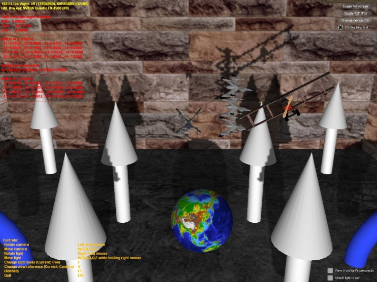
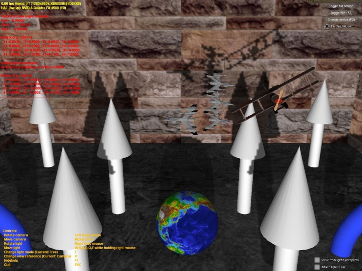
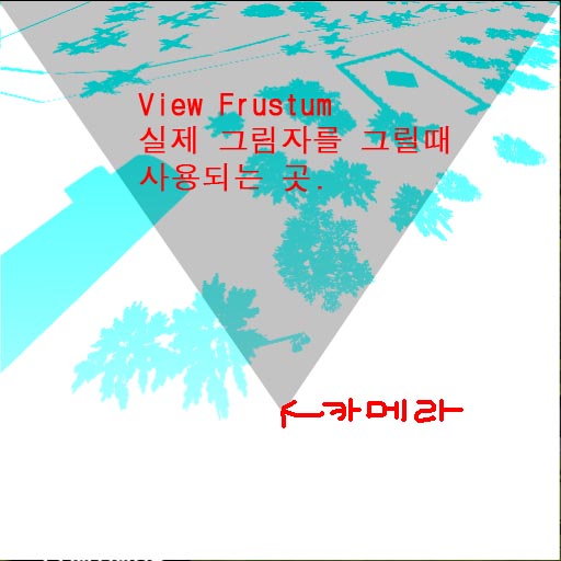
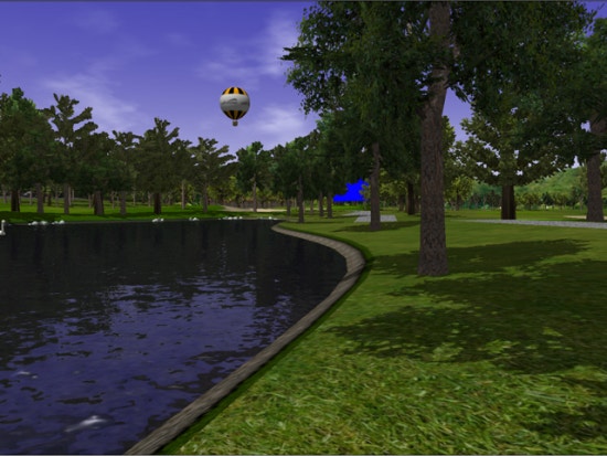
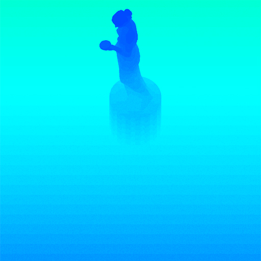
자 봐라! 우리는 그림자 맵을 가지게 되었다. 아래에는 그림자의 색상으로 코딩된 버전이 나와 있다. 어두운 파란색은 깊이 값이 낮음을 의미하고, 밝은 파란색은 깊이 값이 높음을 의미한다.
Setp 2 : Rendering the Shadowed scene into a buffer
다음으로 씬에서 우리는 그림자가 있는 영역을 오프스크린 버퍼로 렌더링할 필요가 있다. 그럼으로써 우리는 그것을 블러링하고 그것을 다시 씬으로 투영할 수 있다. 그렇게 하기 위해서 먼저 씬 내에서 그림자가 있는 영역을 스크린 크기의 고정 소수점 텍스처에 렌더링한다.
if( FAILED( g_pd3dDevice->CreateTexture( SCREEN_WIDTH, SCREEN_HEIGHT, 1,
D3DUSAGE_RENDERTARGET, D3DFMT_A8R8G8B8, D3DPOOL_DEFAULT,
&g_pScreenMap, NULL ) ) )
{
MessageBox( g_hWnd, "Unable to create screen map!",
"Error", MB_OK | MB_ICONERROR );
return E_FAIL;
}
g_pScreenMap->GetSurfaceLevel( 0, & g_pScreenSurf );
projective 텍스처 좌표를 얻기 위해서 우리는 "texture" 행렬을 필요로 한다. 이는 투영 공간으로부터의 위치를 텍스처 공간으로 매핑할 것이다.
float fTexOffs = 0.5 + (0.5 / (float)SHADOW_MAP_SIZE);
D3DXMATRIX matTexAdj( 0.5f, 0.0f, 0.0f, 0.0f,
0.0f, -0.5f, 0.0f, 0.0f,
0.0f, 0.0f, 1.0f, 0.0f,
fTexOffs, fTexOffs, 0.0f, 1.0f );
matTexture = matLightViewProj * matTexAdj;
우리는 깊이 비교를 통해 일반적인 그림자 요소를 획득했다. 그러나 완벽하게 조명이 비춰지는 씬을 출력하는 대신에, 우리는 단지 그림자 요소만을 출력한다. 여기에 그 작업을 하기 위한 정점 및 픽셀 쉐이더가 있다.
struct VSOUTPUT_UNLIT
{ float4 vPosition : POSITION;
float4 vTexCoord : TEXCOORD0;
float fDepth : TEXCOORD1;
};
VSOUTPUT_UNLIT VS_Unlit( float4 inPosition : POSITION )
{
VSOUTPUT_UNLIT OUT = (VSOUTPUT_UNLIT)0;
OUT.vPosition = mul( inPosition, g_matWorldViewProj );
OUT.vTexCoord = mul( inPosition, g_matTexture );
OUT.fDepth = mul( inPosition, g_matLightViewProj ).z;
return OUT;
}
우리는 percentage closer filtering(PCF) 를 사용해 들쑥날쑥한 모서리들을 부드럽게 한다. PCF 를 "수행"하기 위해서는 중심 텍셀을 둘러 싸는 8 개의 주변 텍셀을 샘플링하고(여기에서 우리는 3x3 PCF 커널을 사용한다), 모든 깊이 비교를 이용한다.
float4 PS_Unlit( VSOUTPUT_UNLIT IN ) : COLOR0
{
float4 vTexCoords[9];
float fTexelSize = 1.0f / 1024.0f;
vTexCoords[0] = IN.vTexCoord;
vTexCoords[1] = IN.vTexCoord + float4( -fTexelSize, 0.0f, 0.0f, 0.0f );
vTexCoords[2] = IN.vTexCoord + float4( fTexelSize, 0.0f, 0.0f, 0.0f );
vTexCoords[3] = IN.vTexCoord + float4( 0.0f, -fTexelSize, 0.0f, 0.0f );
vTexCoords[6] = IN.vTexCoord + float4( 0.0f, fTexelSize, 0.0f, 0.0f );
vTexCoords[4] = IN.vTexCoord + float4( -fTexelSize, -fTexelSize, 0.0f, 0.0f );
vTexCoords[5] = IN.vTexCoord + float4( fTexelSize, -fTexelSize, 0.0f, 0.0f );
vTexCoords[7] = IN.vTexCoord + float4( -fTexelSize, fTexelSize, 0.0f, 0.0f );
vTexCoords[8] = IN.vTexCoord + float4( fTexelSize, fTexelSize, 0.0f, 0.0f );
float fShadowTerms[9];
float fShadowTerm = 0.0f;
for( int i = 0; i < 9; i++ )
{
float A = tex2Dproj( ShadowSampler, vTexCoords[i] ).r;
float B = (IN.fDepth ?0.1f);
fShadowTerms[i] = A < B ? 0.0f : 1.0f;
fShadowTerm += fShadowTerms[i];
}
fShadowTerm /= 9.0f;
return fShadowTerm;
}
이 스크린 버퍼는 썩 괜찮다! 이제 이것을 블러링하고 다시 스크린 공간의 씬에 투영할 필요가 있다.
Step 3 : Blurring the screen buffer
우리는 seperable gaussian 필터를 사용해서 스크린 버퍼를 블러링하지만, Poisson 필터를 사용할 수도 있다. 현재의 렌더 타겟은 해당 서피스에 연결된 A8R8G8B8 텍스처이다. 우리는 2 개의 렌더 타겟을 필요로 하는데, 하나는 수직 경로를 위한 것이고 다른 하나는 수평 경로를 위한 것이다.
// 블러 맵 생성
for( int i = 0; i < 2; i++ )
{
if( FAILED( g_pd3dDevice->CreateTexture( SCREEN_WIDTH, SCREEN_HEIGHT, 1,
D3DUSAGE_RENDERTARGET,
D3DFMT_A8R8G8B8, D3DPOOL_DEFAULT,
&g_pBlurMap[i], NULL ) ) )
{
MessageBox( g_hWnd, "Unable to create blur map!",
"Error", MB_OK | MB_ICONERROR );
return E_FAIL;
}
// 텍스처 서피스 획득
g_pBlurMap[i]->GetSurfaceLevel( 0, & g_pBlurSurf[i] );
}
우리는 15 개의 Gaussian 오프셋 및 관련 가중치를 다음 함수들을 사용해 생성했다.
float GetGaussianDistribution( float x, float y, float rho )
{
float g = 1.0f / sqrt( 2.0f * 3.141592654f * rho * rho );
return g * exp( -(x * x + y * y) / (2 * rho * rho) );
}
void GetGaussianOffsets( bool bHorizontal, D3DXVECTOR2 vViewportTexelSize,
D3DXVECTOR2* vSampleOffsets, float* fSampleWeights )
{
// 중심텍셀 오프셋과 가중치 획득
fSampleWeights[0] = 1.0f * GetGaussianDistribution( 0, 0, 2.0f );
vSampleOffsets[0] = D3DXVECTOR2( 0.0f, 0.0f );
// 남은 요소들의 오프셋 및 가중치 획득
if( bHorizontal )
{
for( int i = 1; i < 15; i += 2 )
{
vSampleOffsets[i + 0] = D3DXVECTOR2( i * vViewportTexelSize.x, 0.0f );
vSampleOffsets[i + 1] = D3DXVECTOR2( -i * vViewportTexelSize.x, 0.0f );
fSampleWeights[i + 0] = 2.0f * GetGaussianDistribution( float(i + 0), 0.0f, 3.0f );
fSampleWeights[i + 1] = 2.0f * GetGaussianDistribution( float(i + 1), 0.0f, 3.0f );
}
}
else
{
for( int i = 1; i < 15; i += 2 )
{
vSampleOffsets[i + 0] = D3DXVECTOR2( 0.0f, i * vViewportTexelSize.y );
vSampleOffsets[i + 1] = D3DXVECTOR2( 0.0f, -i * vViewportTexelSize.y );
fSampleWeights[i + 0] = 2.0f * GetGaussianDistribution( 0.0f, float(i + 0), 3.0f );
fSampleWeights[i + 1] = 2.0f * GetGaussianDistribution( 0.0f, float(i + 1), 3.0f );
}
}
}
스크린 버퍼를 블러링하기 위해서 블러 맵을 렌더 타겟으로 설정하고, 스크린 크기의 쿼드를 다음 정점 및 픽셀 쉐이더를 사용해 렌더링한다.
// Gaussian 필터 정점 쉐이더
struct VSOUTPUT_BLUR
{
float4 vPosition : POSITION;
float2 vTexCoord : TEXCOORD0;
};
VSOUTPUT_BLUR VS_Blur( float4 inPosition : POSITION, float2 inTexCoord : TEXCOORD0 )
{
// 출력 구조체
VSOUTPUT_BLUR OUT = (VSOUTPUT_BLUR)0;
// Output the position
OUT.vPosition = inPosition;
// Output the texture coordinates
OUT.vTexCoord = inTexCoord;
return OUT;
}
// 수평 블러 픽셀 쉐이더
float4 PS_BlurH( VSOUTPUT_BLUR IN ): COLOR0
{
// Accumulated color
float4 vAccum = float4( 0.0f, 0.0f, 0.0f, 0.0f );
// Sample the taps (g_vSampleOffsets holds the texel offsets
// and g_fSampleWeights holds the texel weights)
for(int i = 0; i < 15; i++ )
{
vAccum += tex2D( ScreenSampler, IN.vTexCoord + g_vSampleOffsets[i] ) * g_fSampleWeights[i];
}
return vAccum;
}
// 수직 블러 픽셀 쉐이더
float4 PS_BlurV( VSOUTPUT_BLUR IN ): COLOR0
{
// Accumulated color
float4 vAccum = float4( 0.0f, 0.0f, 0.0f, 0.0f );
// Sample the taps (g_vSampleOffsets holds the texel offsets and
// g_fSampleWeights holds the texel weights)
for( int i = 0; i < 15; i++ )
{
vAccum += tex2D( BlurHSampler, IN.vTexCoord + g_vSampleOffsets[i] ) * g_fSampleWeights[i];
}
return vAccum;
}
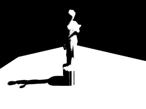
이제 블러 맵이 준비되었다. 그림자의 블러 양을 늘리려면 텍셀 샘플링 거리를 증가시키면 된다. 마지막 단계는 블러링된 맵을 스크린 공간의 씬에 다시 투영하는 것이다.
 첫 번째 Gaussian 패스 이후
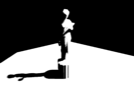
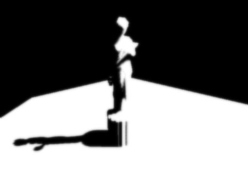 두 번째 Gaussian 패스 이후
Step 4 : Rendering the shadowed scene
블러 맵을 씬에 투영하기 위해서 우리는 씬을 보통과 같이 렌더링한다. 그러나 블러 맵을 스크린 공간 좌표를 사용해 투영한다. 우리는 약간의 하드 코딩된 math 를 사용하는 clip 공간 위치를 사용해 스크린 공간 좌표를 생성한다. 아래에 그림자를 따라 픽셀당 조명을 사용하여 씬을 렌더링하는 정점 및 픽셀 쉐이더가 나와 있다.
struct VSOUTPUT_SCENE
{
float4 vPosition : POSITION;
float2 vTexCoord : TEXCOORD0;
float4 vProjCoord : TEXCOORD1;
float4 vScreenCoord : TEXCOORD2;
float3 vNormal : TEXCOORD3;
float3 vLightVec : TEXCOORD4;
float3 vEyeVec : TEXCOORD5;
};
// 씬 정점 쉐이더
VSOUTPUT_SCENE VS_Scene( float4 inPosition : POSITION, float3 inNormal : NORMAL,
float2 inTexCoord : TEXCOORD0 )
{
VSOUTPUT_SCENE OUT = (VSOUTPUT_SCENE)0;
// 변환된 위치 출력
OUT.vPosition = mul( inPosition, g_matWorldViewProj );
// 텍스처 좌표 출력
OUT.vTexCoord = inTexCoord;
// 투영 텍스처 좌표 출력
// (spot 텍스처를 씬에 투영하기 위해 이를 사용)
OUT.vProjCoord = mul( inPosition, g_matTexture );
// 스크린 공간 텍스처 좌표 출력
OUT.vScreenCoord.x = ( OUT.vPosition.x * 0.5 + OUT.vPosition.w * 0.5 );
OUT.vScreenCoord.y = ( OUT.vPosition.w * 0.5 - OUT.vPosition.y * 0.5 );
OUT.vScreenCoord.z = OUT.vPosition.w;
OUT.vScreenCoord.w = OUT.vPosition.w;
// 월드 공간 정점 위치 획득
float4 vWorldPos = mul( inPosition, g_matWorld );
// 월드 공간 법선 출력
OUT.vNormal = mul( inNormal, g_matWorldIT );
// 조명 벡터를 탄젠트 공간으로 이동시킴
OUT.vLightVec = g_vLightPos.xyz - vWorldPos.xyz;
// 관찰자 위치(eye) 벡터를 탄젠트 공간으로 이동시킴
OUT.vEyeVec = g_vEyePos.xyz - vWorldPos.xyz;
return OUT;
}
우리는 조명으로부터 sopt 텍스처를 투영하기 위해서 부가적인 spot 항을 추가했다. 이것은 집중 조명 효과를 시뮬레이션하기 위한 목적 뿐만 아니라, 그림자 맵 외부의 씬의 바깥쪽 영역을 잘라내기 위한 목적도 있다. 이 spot 맵은 표준 투영 텍스처링을 사용해서 투영된다.
float4 PS_Scene( VSOUTPUT_SCENE IN ) : COLOR0
{
// 법선, 광원, 눈 벡터 정규화
IN.vNormal = normalize( IN.vNormal );
IN.vLightVec = normalize( IN.vLightVec );
IN.vEyeVec = normalize( IN.vEyeVec );
// 색상 및 법선 맵 샘플링
float4 vColor = tex2D( ColorSampler, IN.vTexCoord );
// 주변, 분산, 반사 조명 항 계산
float ambient = 0.0f;
float diffuse = max( dot( IN.vNormal, IN.vLightVec ), 0 );
float specular = pow(max(dot( 2 * dot( IN.vNormal, IN.vLightVec ) * IN.vNormal
- IN.vLightVec, IN.vEyeVec ), 0 ), 8 );
if( diffuse == 0 ) specular = 0;
// 그림자 항 획득
float fShadowTerm = tex2Dproj( BlurVSampler, IN.vScreenCoord );
// spot 항 획득
float fSpotTerm = tex2Dproj( SpotSampler, IN.vProjCoord );
// 최종 색상 계산
return (ambient * vColor) +
(diffuse * vColor * g_vLightColor * fShadowTerm * fSpotTerm) +
(specular * vColor * g_vLightColor.a * fShadowTerm * fSpotTerm);
}
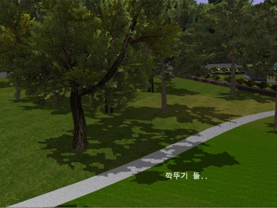
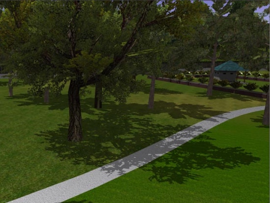
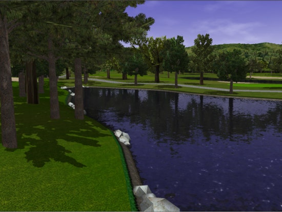
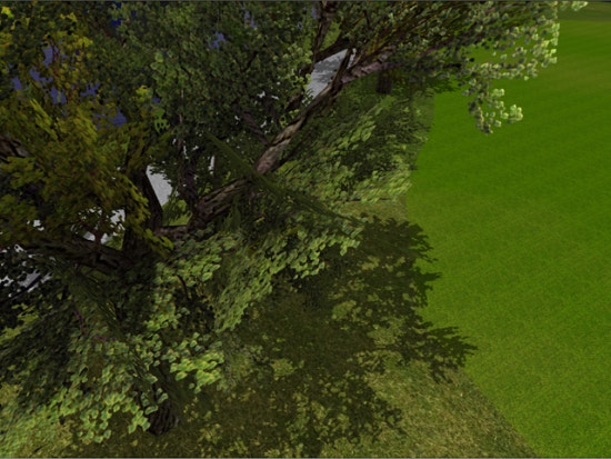
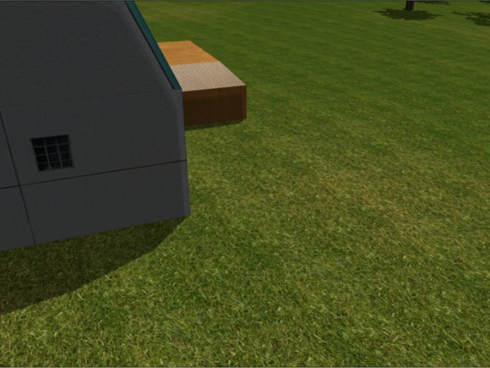
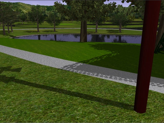
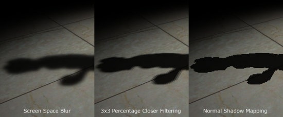
바로 이것이다! 우리는 매우 괜찮아 보이는 부드러운 모서리 그림자를 가지게 되었다. 이 기법의 이점은 완벽하게 그림자 맵의 단점인 모서리 aliasing 인공물을 제거한다는 것이다. 다른 이점은 적은 메모리 오버헤드를 가지고 다중 조명을 위한 부드러운 그림자를 생성할 수 있다는 것이다. 다중 조명을 다룰 때 당신이 할 일은 조명당 그림자 맵을 하나씩 만들어 주는 것 뿐이다. 반면에 스크린이나 블러 버퍼는 모든 조명에 의해 공유될 수 있다. 마지막으로 이 기법은 그림자 맵 및 그림자 부피 모두에 적용될 수 있다. 그래서 그림자 기법에 상관없이 당신은 이 기법을 사용해 부드러운 모서리 그림자를 생성할 수 있다. 단점이 하나 있다면 이 기법은 Gaussian 필터를 사용하기 위해서 fill-rate 에 상당히 민감하다는 것이다. 이것은 작은 블러 버퍼를 사용하거나 가시 품질을 약간 희생함으로써 최소화될 수 있다.
다음은 여기에서 언급한 접근들 사이의 비교이다. 3x3 percent closer 필터링 및 일반 그림자 매핑이다.
Reference
- Hardware Shadow Mapping. Cass Everitt, Ashu Rege and Cem Cebenoyan
- Hardware-accelerated Renderng of Antialiased Shadows with Shadow Map. Stefan Brabec and Hans-Peter Seidel.